RF Cable Testing
Contents
1. Cable Testing
2. Cable Assembly - a brief introduction
i. Visual Inspection
ii. A typical test scenario
iii. Crimp vs Solder
iv. Cable Preparation and Assembly
v. Cable Testing
vi. Electrical Measurements
vii. Return Loss Measurement
viii. Return Loss Calibration
ix. R/L Measurement
x. Velocity of Propagation
xi. Characteristics Impedance
xii. Time Domain Reflectometer Measurements
xiii. Capacitance Measurement
xiv. Inductance Measurement
3. Conclusion
Suppose you are a system designer (working on a RF project) and have arrived at the system budget by performing system calculation, and have identified the various RF subsystems, which will be a part of the system. In the process, you have identified and selected the electronic components (like the discrete RF modules, MMICs, resistors, capacitors etc) that will be part of the BOM. The list includes also includes a set of RF cables and connectors to be used as interconnect system. While our attention is focussed more towards the electronic components, as a system engineer, you realize that selection and procurement of cable assemblies is paramount to the success or failure of the project. In the process, the system engineer interacts with a cable manufacturer for the selection of the right cable assembly (cable and connector assembled together).
The next question, is how will you test a cable once it arrives at your lab? What are the critical electrical and mechanical characteristics of a RF cable? How are we going to test them? What test and measurement equipment to use?
Before we delve into the testing methods of a cable, it is necessary to identify another important aspect: that is, the tools and jigs used for the cable assembly. We are assuming here, that the cable has arrived in its raw form, and a lab technician is going to assemble it. We also assume the technician is experienced in cable assembly process and has performed this task for a variety of cable and connector combination. We will also list down some of the important tools and accessories needed to perform cable assemblies.
Cable assembly is a process of identifying, preparing and fixing a coaxial cable with a suitable coaxial connector system.
The process of identifying involves study and evaluation of the system requirement such as: the intended application, electrical characteristics, mechanical characteristics, environmental stress and cost budget. Please refer to the "Cable" article on www.rfcables.org for a detailed description of cable identification process.
Once a cable has been identified and procured (involves interaction with the cable manufacturer etc), it has to be tested electrically, physically and for mechanical properties. It is to be noted that, there are third party agencies, whose services could be utilized in testing the cable. For example, ETDC (Electronic Testing and Device Characterisation), Bangalore, offer such services. The services include electrical, mechanical and environmental stress testing of products such as a cable assembly, amplifier, RF transmitter etc. However, for the sake of inclusion, we will list down some of these tests to be performed. It is also assumed in this article that the reader is familiar with the electrical testing parameters such as Insertion loss (attenuation), VSWR (return loss), cross talk, RF leakage etc. If necessary, the reader may refresh on these topics at our website www.rfcables.org. It is also assumed that the reader is familiar with the T&M (test and measurement) equipments (including test chambers such as walk-in chamber and vibration chamber used for environmental testing) from popular vendors (HP/Agilent, Anritsu/Wiltron, Rohde & Schwartz) such as Vector and Scalar network analyzer, Time Domain Reflectometer (TDR), Spectrum Analyzer, signal generator, oscilloscope, power meter, precision test cable, connector and the calibration kit.
After the cable identification and procurement, a brief visual inspection of the physical cable is adequate to ensure that the type ordered and the one procured are same in terms of look and feel. Suppose, the cable in question is a 1 in diameter feeder cable with an outer PVC jacket for outdoor installation, then it is not difficult to verify this with a cursory visual inspection. Or verifying if the cable has a copper plated aluminium center conductor, by looking at the cross sectional cut out of the cable. Likewise, one can visually verify the type of insulator (although may not be conclusive as dielectrics may have similar physical appearance) and the outer conductor shield: whether braided, corrugated or solid foil.
Next, comes the cable preparation phase - a phase in which, the cable assembly process begins; by preparing the cable for the final assembly. Usually, a cable assembly drawing is made detailing its construction and different parts used in its assembly. The system designer also derives inputs from the cable and connector manufacturer's catalogue.
For example, a system designer (in his system design calculation) has budgeted a 2 dB loss (including 0.5 db connector loss at both ends of the cable) between the amplifier output and the antenna port input of a radio transmitter. A flexible 50-ohm cable of the type RG59 has been selected for this application, based on the return loss and power handling capability of this cable. Since, this cable connects the power amplifier with the antenna, a good impedance match (return loss greater than 20 dB) and power-handling capability (assuming 2 watts of CW power, say, at 2 GHz power amplifier output) is expected out of this cable. In this application, the two most important feature of the cable testing are the return loss and the attenuation/insertion loss characteristics of this cable. Assuming the PA delivers an output of + 33 dBm, the system engineer has factored-in a cable drop of 2 dB in his system budget calculation. Hence, we expect a CW power of + 31 dBm at the input of the antenna port. The purpose of testing the cable becomes evident. It has to be tested for an insertion loss or the power drop in the operating band of frequency. This drop also determines the length of the cable to be prepared. A poor cable connection at the antenna port will result in an impedance mismatch leading to a fraction of the power being transferred from the amplifier output to the antenna for transmission.
Having elaborated on the need for cable testing, we turn our attention to some of the cable assembly practices followed in the industry. One such aspect of a cable assembly is that of the method used for assembling the cable and the connector. Two popular methods, namely, 'Soldering' and 'Crimping' are discussed here.
Crimping is a solder less process in which the cable and the connector are joined together using compression force - the center pin of the connector is joined or crimped to the center conductor of the cable and the outer shell of the connector to the cable shield. Crimping is a process wherein a joint is accomplished by compressing the surfaces of two conductors.

This is done manually by compressing the respective conductor joints, by a specified amount of force, using a special tool called the Crimping tool. In a solder joint, as the name suggests, the respective conductor joints are soldered using a temperature controlled soldering iron and tin lead. The soldering iron uses the correct inserts (tips attached to the solder iron rod) and a good quality lead (tin alloy). In both the cases, it is important and advisable, to follow the guidelines issued by their respective manufacturers.

Both these methods, ultimately aim for a stable cable-connector joints and the expected electrical performance over a long period of time or a number of cycles of operations. They are also expected to meet the functional and operational standards required (for example MIL-SPEC) when subjected to environmental and mechanical stress testing. While, crimping process is faster as compared to soldering (other similar processes involve brazing and welding; for cables designed with materials that can be connected only at higher temperatures giving a very stable joint), a badly crimped cable is a total waste and cannot be reused. It is important to select the right crimping tool (correct die with correct geometry and size, correct compression force for a ratchet type of crimper) as much as follow the cable assembly instruction. A skilled technician, on the other hand can assemble a cable, using a good soldering technique, which has flawless center pin, and outer shield solder joints (such as uniform, flat, shiny and not brittle or dry joints or wick and does not have excess solder spill over in the form of blobs of solder lead sticking out at the joints). However, in a large-scale production environment, to make the cable assembly process faster, crimping is a preferred method of cable assembly. It is a common practice in a production house to design and fabricate a mechanical jig to augment the cable assembly process. Such as jig may consist of a placeholder for the cable and a mechanism to align and held together the connector and the cable joint, for an effective crimping. In some cases, cable joints are crimped first and then soldered but not the reverse, as a soldered joint because of its surface properties cannot be crimped.
Hence the next phase in the cable assembly process is - cable preparation. Cable preparation refers to the cutting of the cable in such as way, so as to expose the center conductor, the insulator (dielectric) and the outer conductor, by a process involving cutting and stripping. Stripping the outer conductor braid cleanly ensures that there are no burs, cutting the insulator dielectric material at 90 degrees to the surface of the center conductor, with the specified length exposed, ensures a good cable cut. A knife blade or a cutter is used to cut the center conductor of the cable cleanly.
For preparing a cable, we need a set of tools suitable for carrying out this task. We shall mention some of the tools and jigs used for the cable preparation. These tools are crimping tool, stripper, knife or a blade, soldering station, lead and tin etc.
As mentioned a cable is assembled with the connector using crimping or soldering technique. After the cable has been prepared and the joints have been made, the cable assembly is ready to be tested.
Cable testing involves familiarity with T&M equipments, the calibration procedure, collating and analysis of the test results, familiarity with standards such as HPIB and GPIB for networking the instruments with a central computer etc. Most importantly, a test engineer should be familiar with various types of precision connectors, adaptors and cables used in these measurements.
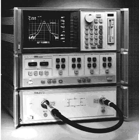
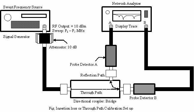
A swept frequency measurement using a network analyzer (NA) determines the insertion loss and return loss of the cable assembly in the desired frequency band of operation. A sweep signal generator drives the X and Y sweep inputs of the network analyzer for the swept frequency of operation in the desired band. For this reason, the swept output of the X, Y ports on the signal generator are connected to the swept input ports X and Y of the network analyzer using BNC cable. The instrument set up also uses a Bridge or a directional coupler, which has three ports, namely: input port, the output port and the reflected port. The input port to output port is referred to as the "Through" port or the insertion loss port and the third port as return loss port. The network analyzer has two measurement channels, A and B. Channel A is generally used for insertion loss measurement and B for return loss but these can be interchanged. The sweep signal generator is appropriately adjusted (by using fixed pads or variable attenuator if necessary) to give a flat power output over the desired frequency band. The power output of the signal generator is connected to the input port of the directional coupler or the Bridge. The DUT (in this case the Cable-Under-Test or CUT) is inserted between the output port (through port) of the Bridge and the probe detector of the channel A. The probe detector is attached to a cable, which in turn is connected to the channel A input of the Network analyzer front panel. This through path is used to measure the insertion loss, when the CUT is inserted between the bridge and channel A detector.

 |
 |
Fig. A view of a typical Network Analyzer set up and the accessories
Similarly, the return port of the bridge is connected to a probe detector, which is attached to a cable connected to B input port of the network analyzer. This reflection path is used to measure the return loss of the CUT port. Please note that, in this arrangement, we will measure the R/L of the CUT port, which is currently connected to the bridge output port. In order to measure the R/L of the other end of the cable port, the cable has to be reversed and reattached to the bridge output port and the measurement repeated. This is so, because although a cable appears to be having the same cable-connector connection on both the ends, they are unique connections (connector-cable combination), and both the ends need to be measured for return loss.
T&M Equipment required
-
Scalar network analyzer
-
Sweep signal generator
-
A directional bridge
-
Two probe detectors
-
Calibration kit - standard short, open, load, precision connectors, adapters
Return loss (R/L) measurement is performed on the CUT, by first carrying out the calibration process. Calibration involves measuring known standards and using those measurements to compensate for systematic errors. Calibrations can be simple (such as compensating for transmission line length) or involved methods that compensate for losses, mismatches, and feedthroughs. A network analyzer (or its test set) will have connectors on its front panel, but the measurements are seldom made at the front panel. Usually some test cables will go from the front panel to the device under test (DUT) such as a two-port filter or amplifier. The length of those cables will introduce a time delay and corresponding phase shift (affecting VNA measurements); the cables may also introduce some attenuation (affecting SNA and VNA measurements). A calibration process sets up the measurement in such a way that the results obtained after the calibration process is done, is that of the CUT only. This means, we calibrate out the cables and directional bridge involved in the test set up, for any systematic errors.
For return loss calibration, the output port of the directional bridge is first terminated by a short precision connector, the R/L trace saved and calibrated by operating the respective buttons on the NA front panel. Next, an open connector is connected and the procedure of obtaining the R/L trace repeated. Both open and short connectors are to be used from the calibration kit available with the NA. This process sets up the 0 dB reference level mark on the channel B display of the network analyzer. This completes the calibration process for the R/L measurement.
Next, one of the connector port sides of the CUT is connected to the bridge output port. The other connector port side of the CUT is terminated into a 50-ohms termination load connector. On inserting the CUT, the channel B display of the return loss shifts down from the 0 dB reference mark. The R/L display scale is adjusted to 10 dB/div or 5 dB/div so as to display an accurate R/L reading over the swept frequency band. Using and moving the cursor knob on the N/A panel, the return loss can be measured or read off directly from this display at any frequency within the band. The R/L trace taken over the frequency band may exhibit few 'kinks' or dips at certain frequencies. The dips can arise due to the resonance effect of the travelling RF energy inside the coaxial cable at that frequency. This indicates the combined effect of the connector and cable. A flat R/L trace of 20 dB ± 1 dB shows a good cable electrical performance (and hence quality of cable and connector and their assembly) over the entire band. To measure the R/L of the other end of the cable, it has be removed and reversed. The cable port, which was earlier 50-ohm terminated, is now connected to the bridge and the port, which was earlier connected to the bridge, is now terminated into 50-ohms termination load connector. The input and output side of the CUT is swapped. The R/L display on channel B, now, indicates the electrical performance of the second cable port. The value and flatness of the R/L trace indicates the electrical performance of the cable-connector and its assembly.


The velocity of propagation determines the resonances or troughs attained at distinct frequencies in the specified band. The resonances occur due to the dielectric properties of the coaxial cable medium and the permeability of the conductor, when the RF energy travels through it. The calculation is based on the MIL-C-17 standard.
The measurement set up is similar to the return loss measurement set up except for a minor deviation as explained below. The reflection port of the bridge is connected to the channel A of the N/A and the through path is connected to the one end of the CUT. The other end of the CUT is left in open circuit condition. The start and stop frequency is set on the signal generator at a nominal power and the same is set on the N/A trace. The number of observable data points is determined as the cable is swept between the frequencies set. If required the IF bandwidth on the N/A is adjusted to observe a series of resonances between the start and the stop frequencies. The first three consecutive resonances appearing after the start frequency are noted down. The resonance points are the troughs as seen in the N/A trace. By changing the frequency span and the center frequency on the N/A, more accurate measurements of the resonances can be observed and recorded at these frequencies. These accurate frequencies are used to calculate the velocity of propagation.
Time domain reflectometry (TDR) principle is used to determine the characteristic impedance of the CUT. TDR involves transmitting a short rise time pulse through the CUT and measuring the reflected pulse arising due to a discontinuity in the cable assembly, by comparing it with the incident pulse. If the conductor of the CUT is of uniform impedance and properly terminated, the entire transmitted pulse will be absorbed in the far-end termination and no signal will be reflected toward the TDR. However, any impedance discontinuities will cause a fraction of the incident signal to be reflected back towards the source. The resulting reflected pulse that is measured at the TDR is displayed or plotted as a function of time. Since the velocity of propagation is taken as a constant for the given CUT, it can be read as a function of the CUT length. Due to the sensitivity to impedance variations, a TDR may be used to verify cable impedance characteristics
Equipment required
-
A digital sampling oscilloscope such as Tektronix 11801
-
A sampling head such as SD-24 TDR sampler
-
A standard APC 3.5 mm precision air-line connector & 50 ohm coaxial cable

Tektronix digital sampling oscilloscope 11801C when used with Sampling head SD-24 is used for TDR characterization. SD-24 is a 20 GHz dual channel TDR/Sampling head. The reflected rise time of the TDR is set to 35 ps. An air-line is connected between the TDR and the CUT. The characteristic impedance of the CUT is measured by comparing it with the air line.

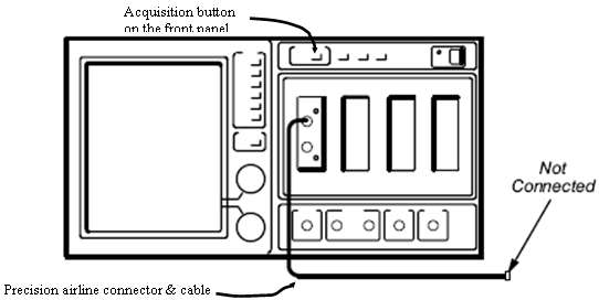
The standard APC 3.5 mm precision 50-ohm air-line connector is connected to one of the channel of the SD-24 through a 50-ohm coaxial cable, and the other end of the air-line is connected to the sample CUT.

(a) Precision airline connected to the sampling head for Initialisation

(b) Getting Waveform trace for the CUT
Equipment Required
-
HP 4194A Impedance/Gain-Phase Analyzer
-
Four port to two terminal adapter

The capacitance of the coaxial cable is specified in Pico farads per foot of the cable under test. It is measured at 1 KHz frequency. For the coaxial cable under test, it is measured between the inner and the outer conductor, with the outer conductor held at ground potential. The analyzer set up includes an impedance measurement probe capable of making high-speed measurements.
A four port to two-terminal adapter is connected to the four impedance terminals of the analyzer. Next the analyzer is set to a frequency span of 1 KHz and the number of data points is chosen. The function is set to impedance (capacitance) mode and channel A is selected for the measurement. The impedance probe is connected to the channel A, while the channel B display is switched off. An open/short calibration of the analyzer is performed. The CUT is connected to the two terminals of the adapter and the capacitance measured for the length of CUT. This reading is converted into capacitance per unit length and expressed as Pico farads per foot or meter.
Inductance measurement of the CUT is carried out in a similar fashion as the capacitance measurement using the same T&M set up. The measurement mode is changed to impedance - inductance measurement mode and an open/short calibration of the analyzer carried out. The analyzer is set to a frequency of 1 KHz and a span of 1 KHz. The electrical length of the CUT is chosen to be at least 1/8 th of the wavelength long. The cable inductance is expressed as nano henries per foot or meter.
The cable testing approaches (by no means these are exhaustive, but are indicative set of popular measurement practices, which a designer should be aware of) discussed in this article gives a fair idea about the electrical characteristics of a coaxial cable. There are far more stringent cable tests conducted at the manufacturer's end, such as high-pot (or high potential), tensile strength, and environmental tests. Some of these environmental tests are carried out in extreme conditions (Temperature: - 55 to + 125 degrees centigrade, humidity, salinity etc.) inside test chambers.